
buck How does a boost converter allow for a gain in output voltage by just switching the
The buck-boost transformer size can be calculated as follows: P = I ×E 1000 = 17.5× 32 1000 = 0.560 kV A P = I × E 1000 = 17.5 × 32 1000 = 0.560 k V A. A buck-boost transformer larger than 0.560 kVA can be installed to boost the voltage to the required level. When both loads are turned on, the voltage at the loads is 120.3 V.
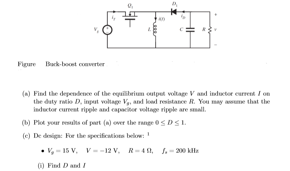
Solved Figure Buckboost converter (a) Find the dependence
The buck-boost converter is a type of DC-to-DC converter that has an output voltage magnitude that is either greater than or less than the input voltage magnitude. It is equivalent to a flyback converter using a single inductor instead of a transformer. [1] Two different topologies are called buck-boost converter.
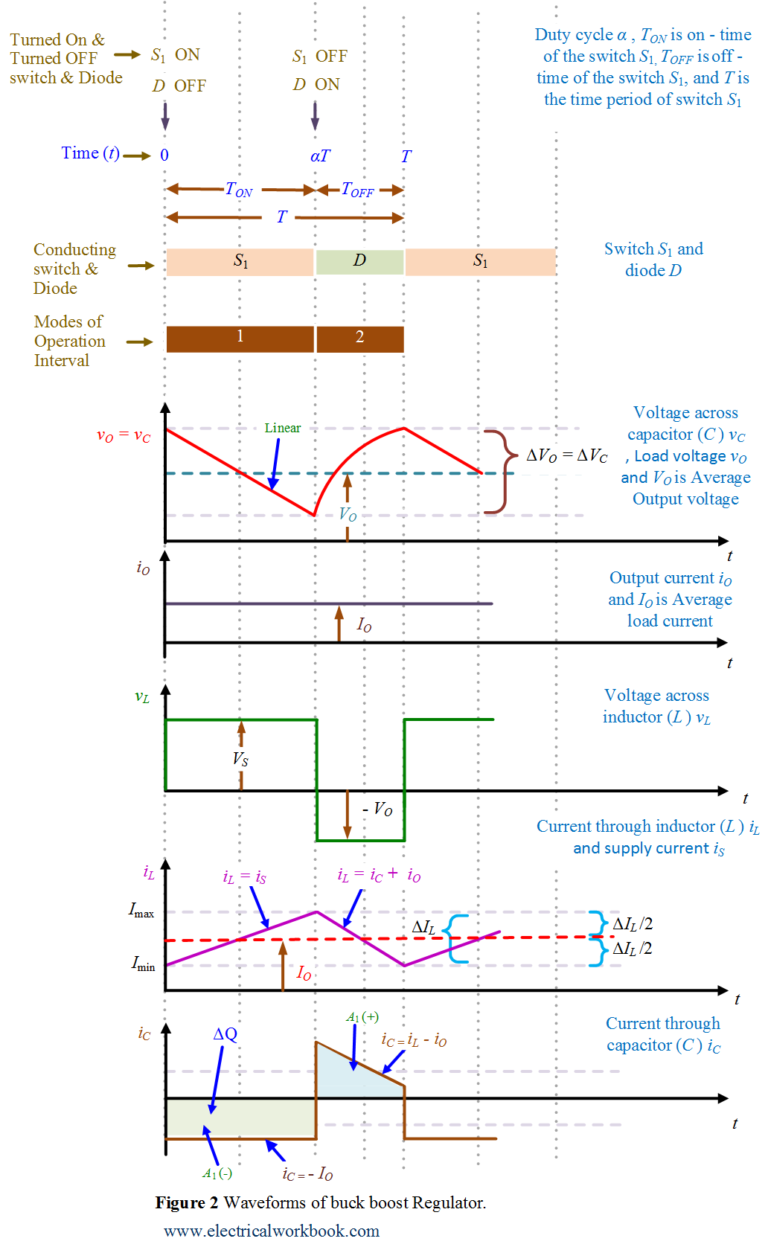
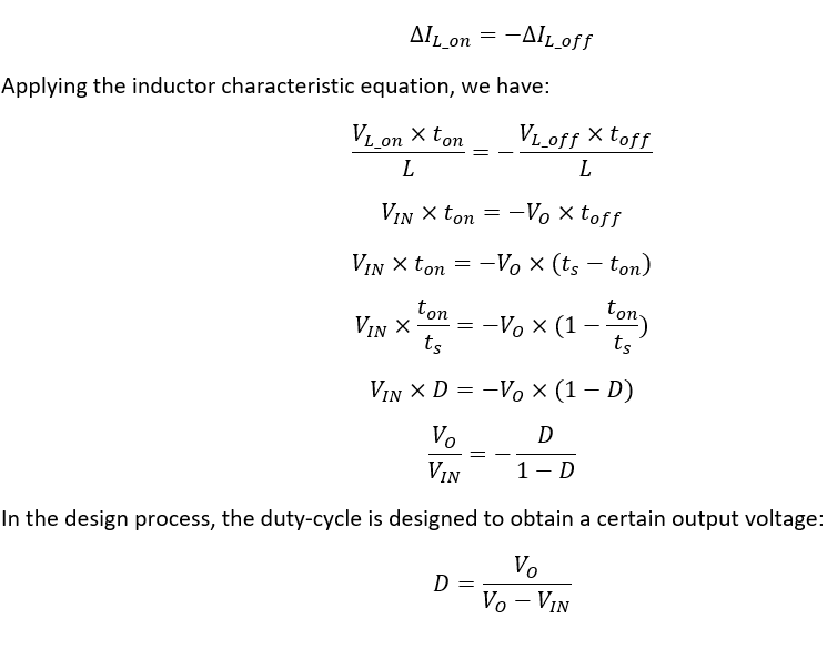
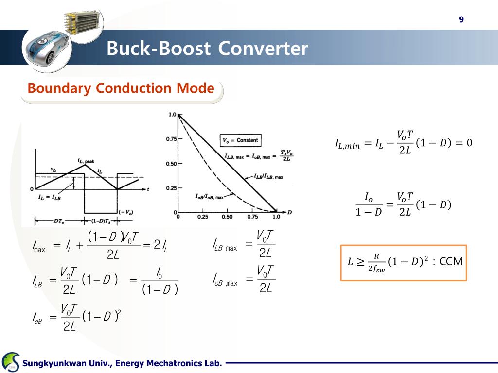
Buck Boost Regulator Peak to Peak Ripple Current of Inductor Expression Derivation
With external compensation, a solution that satisfies both buck and boost mode must be chosen. Follow both sections 7.1 and 7.2 to develop minimum output capacitance for both buck and boost mode operations. Select output capacitance that is larger than both minimum required output capacitance for buck and boost mode operation.
Solved Figure Buck Boost Converter A Find The Dependenc Images
ABSTRACT This application note gives the equations to calculate the power stage of a non-inverting buck-boost converter built with an IC with integrated switches and operating in continuous conduction mode. See the references at the end of this document if more detail is needed. For a design example without description, see appendix A. Contents

Buck Boost Converter Design Equations Tessshebaylo
The following four parameters are needed to calculate the power stage: Input voltage range: V IN(min) and V IN(max) Nominal output voltage: VOUT Maximum output current: I OUT(max) Integrated circuit used to build the buck converter. This is necessary because some parameters for the calculations must be derived from the data sheet.
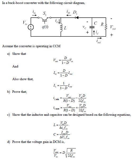
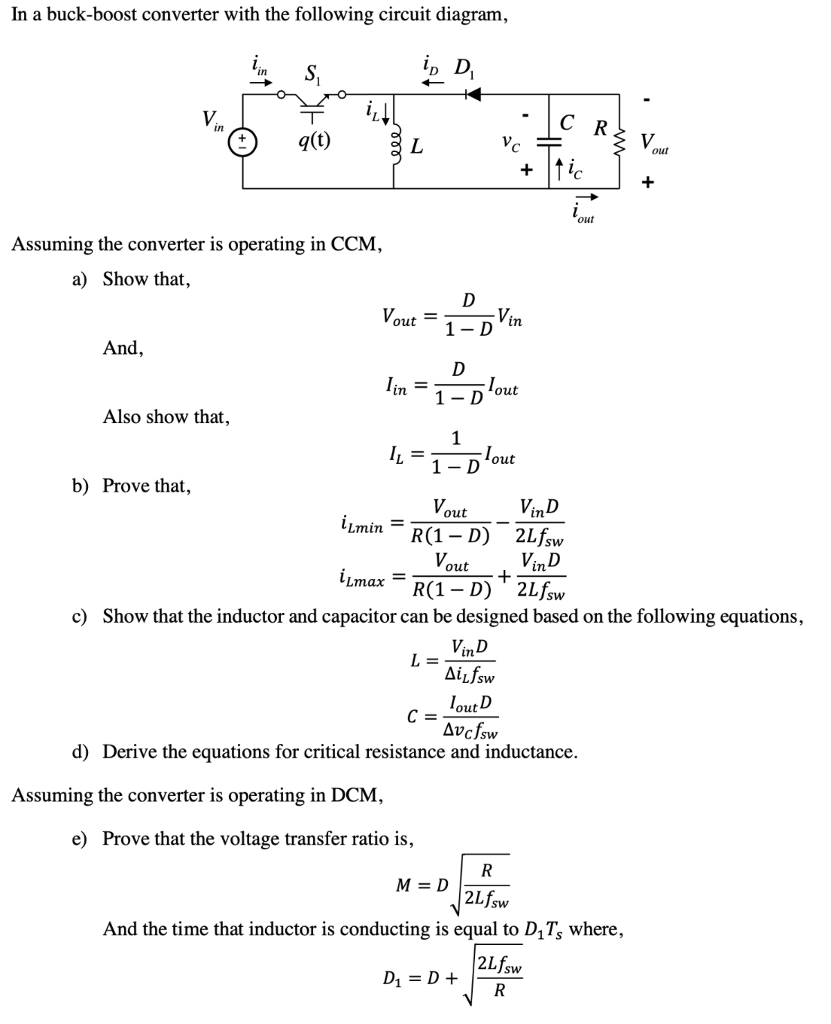
Solved In a buckboost converter with the following circuit
The buck-boost converter is a type of DC-to-DC converter (also knownas a chopper) that has an output voltage magnitude that is either greater than or less than the input voltage magnitude. It is used to "step up" the DC voltage, similar to a transformer for AC circuits.
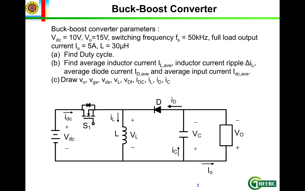
Solved BuckBoost Converter Buckboost Converter Paramete...
A buck-boost converter is an essential power electronic device that operates in both buck (step-down) and boost (step-up) modes. This versatile converter regulates the output voltage at a constant level, regardless of the input voltage, ensuring a stable supply to the connected electronic devices.

Buck Boost Converter Design Equations Tessshebaylo
Efficiency Parameters. From these equations, the following parameters can be used to improve the efficiency of a buck converter. Keep in mind that typically the output voltage and current are.
The power losses and the efficiency of the BuckBoost Converter are achieved with the aid of the
The four basic DC-DC converters considered for analysis are the following: Buck Converter, Boost Converter, Buck-Boost Converter and Ćuk Converter. This technical article deals with the analysis of the four fundamental DC-DC converters (or choppers) in equilibrium.

BuckBoost Converter Voltage Equation in Discontinuous Conduction Mode (DCM) YouTube
Buck-Boost Switching Regulator. The Buck-Boost switching regulator is a combination of the buck converter and the boost converter that produces an inverted (negative) output voltage which can be greater or less than the input voltage based on the duty cycle. The buck-boost converter is a variation of the boost converter circuit in which the.

Schematic diagram of buck, boost, and buckboost converter (a) buck... Download Scientific
Basic Calculation of an Inverting Buck-Boost Power Stage IlonaWeiss ABSTRACT This application note provides basic formulas that you need to design the power stage of an inverting buck-boost converter. The premise is that the power switch is integrated in the IC and the rectification is done by a diode (non-synchronous power stage).
Buck Boost Converter HardwareBee Semipedia
Here, we introduce the buck-boost converter topology and it's two switching operation modes. We derive the relationship between the input voltage, average ou.

Some properties of buck, boost and buckboost converters. Download Scientific Diagram
common use of buck-boost converters are for high power LED lighting where, for example, lead-acid batteries supply a nominal 9-14V to a constant 12V LED load. Conclusion The technology of buck, boost, and buck-boost converters are utilized around the world to provide regulated low-voltage DC/DC power in nearly every electronics market. RECOM's
Schematic Of Buck Boost Converter Wiring Diagram and Schematics
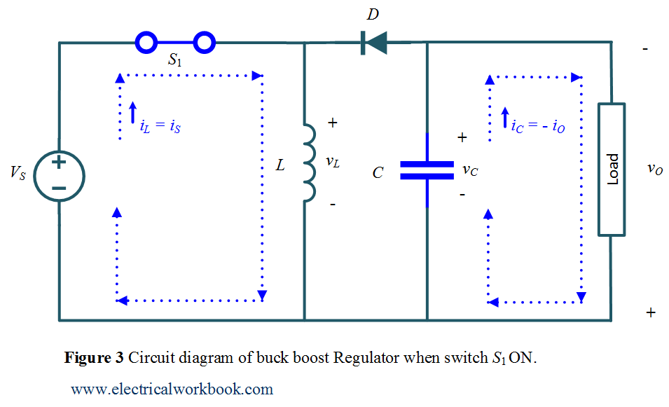
A buck-boost converter provides an output voltage that can be either less than or greater than the dc input voltage V S. Hence the name "buck boost". The output voltage polarity is opposite to that of the input voltage. It is a combination of buck and boost converters. Figure 1: Circuit Diagram of Buck Boost Converter.
PPT DCDC Converter(II) (BuckBoost & Cuk ) PowerPoint Presentation ID1595892
A buck converter (buck converter) is a DC-to-DC power converter that lowers the voltage from the source to the load (in drawing a smaller average current).A boost converter or a DC boost chopper is another name for a DC boost converter.
Stability Analysis of Feedback Loops Part Two
This application note gives the equations to calculate the power stage of a boost converter built with an IC with integrated switch and operating in continuous conduction mode. It is not intended to give details on the functionality of a boost converter (see Reference 1) or how to compensate a converter.